

Future Space Mission Design
INSTITUTION
Cleveland State University
CLASS
Copper Class (2021 – 2022)
STUDENT TEAM
SCIENTIFIC AND TECHNICAL GUIDANCE
Dr. Cassie Bowman, Associate Research Professor, School Of Earth and Space Exploration, ASU
Mr. Phillip Poinsatte, Aerospace Research Engineer in the Turbomachinery and Turboelectric Systems Branch at NASA Glenn Research Center at Lewis Field, in Cleveland, Ohio
Mr. Douglas Thurman, Aerospace Research Engineer in the Turbomachinery and Turboelectric Systems Branch at NASA Glenn Research Center at Lewis Field, in Cleveland, Ohio
ACADEMIC GUIDANCE
Bogdan Kozul, Assistant Professor of Practice in the Department of Mechanical Engineering for Cleveland State University
PROJECT DESCRIPTION
Psyche is an asteroid found in our solar system that is believed to be the remains of a planetesimal, which is a small leftover portion of a planet that was destroyed. Studying Psyche and other planetesimals is a subject of great interest, as they are believed to hold the very building blocks of planetary formation. Research and analysis of the characteristics of this asteroid is the goal of NASA and Arizona State University’s Psyche orbiter.
While the mission plan for the spacecraft is already determined as it is scheduled to launch in August of 2022, it is reasonable to assume that NASA would one day return to Psyche to conduct further research. As a group, our goal is to design various components that would aid in the execution of this hypothetical future mission. The students at Cleveland State University were split into two teams, with one focusing on designing a landing system, and the other focusing on a sample return system.
LAnding System Design
The design incorporates both inspirations of shape and interior composition into one lander. It incorporates a cylindrical-tubular shape and angled sweep into the body of the probe. This design incorporates the use of the crush impact absorption in the interior of the leg components and the use of the socket joints for both the foot of the lander and the legs of the lander. Three internal impact absorption legs (two small arms and one primary landing leg) are angled to absorb impact force when landing. This design also includes two socket joints on the ends of the two small arms of the landing leg to allow for more articulation of the leg when contracting on impact. Similarly, a pin joint was added to the top of the primary landing leg component to account for more extreme landing configurations. Figure (1) shows the full view of the Final Design as well as all the components of the landing gear. Figure (2) shows the cross-section view of the primary landing leg of our design. Figure (3) shows the cross-section view of a small arm of this design.
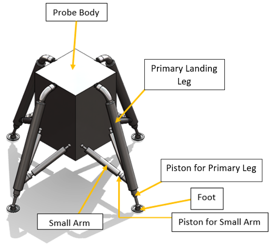
Figure (1) – Final Design: Full view
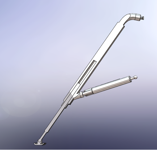
Fig. (2) – Final Design: Primary Landing Leg Cross-Section View
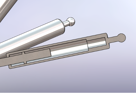
Fig. (3) – Final Design: Small Arm Cross-Section View
Our first challenge was finding a reliable method of energy absorption that could be used in deep space missions. After much research, we decided to employ the use of an aluminum honeycomb mesh to absorb energy. The main concept behind this method of energy absorption is that kinetic energy will be converted into internal energy through the plastic deformation of these aluminum crush-cores. More detailed information regarding the sizing of the crush-cores can be seen in our report, but the short version of the story is that using 32 inches of deformation distance our design is able to withstand an impact of 7 m/s while experiencing a gravitational load of only 30 m/s².
The surface of Psyche-16 is expected to consist of numerous hills and slopes, making the existence of an ideal landing location very unlikely. We must ensure that our design accounts for this challenge in order to regard it as a success.
To account for this problem, we decided to employ the use of ball-joints to attach footpads to the landing legs, as seen in Figure (4). The use of ball-joints in our application allows for ~33 degrees of rotation with 3 degrees of freedom. This allows our landing system to safely land in a variety of configurations depending on the landing location. The use of a ball-joint is also useful when landing on a celestial body because the gravity of the body will naturally align the footpads to be parallel to its surface.
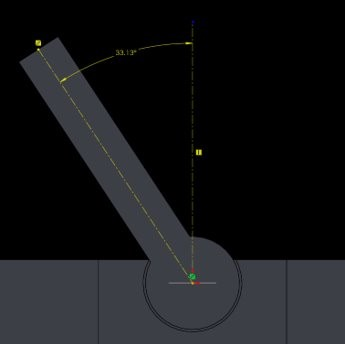
Fig. (4) – A Cross-Sectional View of the Ball-Joint Connecting the Footpad and Landing Leg, showing Rotational Freedom of 33.13°
As a precautionary measure, we also decided to include secondary aluminum crush-cores in our design, which act as a structural attachment to the body as well to absorb any residual lateral motion experienced at impact.
We used computational finite element analysis within SolidWorks to test the viability of our design. Static and buckling analysis was done under the assumption of the worst-case scenario in which only one of our four landing legs can be used.
A. Static
To evaluate the strength and flexibility of the design, static testing was initiated in Design III using SolidWorks. Due to the impact when landing on Psyche, the chosen force to apply to both the top of the design and the foot of the lander is 60,250 N. The fixed points on this object were the bottom part of the top connection and the socket joints of the small arms of the design. We ran simulations using two materials, stainless steel (ferritic), and stainless steel AISI 304.
As a result of the Static Simulation on ferritic stainless steel, the lander was able to withstand the allotted force with minimal bending in any member of the design. In Figure (5), the blue highlighted areas show the lowest amount of stress, while red areas show the highest. As shown, the full object is highlighted in blue, thus this design will withstand the 60,250 N of force enacted on both the top of the leg and bottom of the footpad.
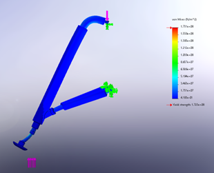
Fig. (5) – Static Simulation of Design III Using Ferritic Stainless Steel with a Deformation Scale of 112
In our second iteration of the simulation, we used AISI 304 stainless steel and found that equivalent results were obtained.
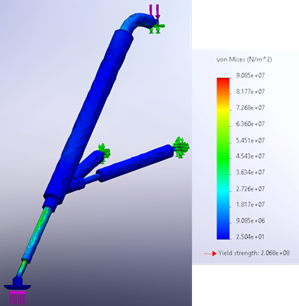
Fig. (6) – Static Simulation of Design III using AISI 304 Stainless Steel with True Deformation Scale
B. Buckling
Simulation testing of buckling was done to measure the landing system’s resistance to bending under compressive load. We ran the simulation using varied materials, much like the static load simulation. The simulation results are multiplied by a scale factor to more easily identify the areas subject to bending.
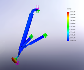
Fig. (7) – Buckling Simulation of Design III Using Ferritic Stainless Steel with a Deformation Scale of 123
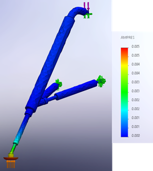
Fig. (8) – Buckling Simulation of Design III Using AISI 304 Stainless Steel with a Deformation Scale of 1
C. Factor of Safety
The final part of the analysis of this design includes the factor of safety. To ensure that the design will not fail, the safety factor must be greater than 0. According to static analysis, the minimum factor of safety in our design was about 2.3 as seen in Figure (9). Considering our design will not be transporting any precious cargo such as human life, we consider the factor of safety as sufficient.
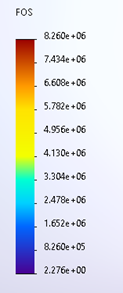
Fig. (9) – Static Factor of Safety of Design III using AISI 304 Stainless Steel
Buckling analysis resulted in a buckling factor of safety of 127.17, as seen in Figure (10), which is more than sufficient to consider this design successful.
![]()
Fig. (10) – Buckling Factor of Safety of Design III Using AISI 304 Stainless Steel
To replicate the high-tech cameras used on previous missions, considerations were made in the design phase to find the best camera possible. The camera used for the hypothesized landing system was the ‘SEN0305 HuskyLens: OV2640’. This five Megapixel camera is capable of object tracking, object recognition, and object classification through Machine Learning, which involves manually selecting identifying features for an object and fine-tuning them.
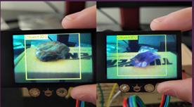
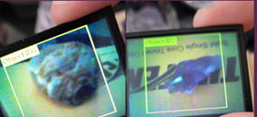
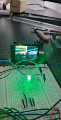
Fig. (11) – HuskyLens object identification
A secondary method to help the landing system safely navigate is via Light Detection and Ranging (LiDAR) devices. The LiDAR device can determine ranges across variable distances by emitting a wave of infrared light on a periodic basis through the Time-of-Flight principle (TOF). The LiDAR device used for this system was the SJ-PM-TF-Luna A03. The LiDAR incorporates a distance range from 20 cm to 8 m and anything below 20cm is considered the dead zone, any measurement below this threshold is unreliable. The LiDAR system was programmed in C++ and was powered through an Arduino Uno microcontroller as seen in Figure (12).
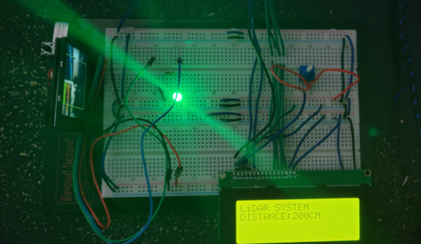
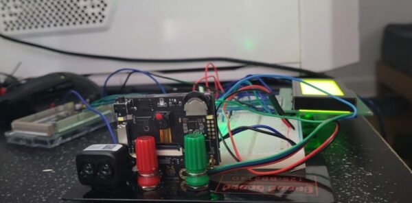
Fig. (12) – LiDAR System Layout
With both the LiDAR and HUSKY systems programmed, we can accurately navigate distance and decent, differentiate materials, classify objects, and much more. With the HUSKYLENS being able to differentiate objects in real time and track positioning, this gives the landing system a distinct advantage over its ancestors. In comparison, the Apollo 11 launched in 1969, and had a single-eyed view of the lander as it made its decent to the surface. It was a single camera mounted on the satellite, and with the aid of a lunar map they were able to successfully land. However, in 2022, the perseverance rover had a total of 23 cameras. Giving its team unprecedented visibility into Mars Landing in real time. These cameras have allowed us to gain a better understanding of what exactly happened as a landing system nears the surface. These cameras were mounted on various parts of the spacecraft, including the back shell, heatshield, and parachute system; all visible in real-time. Design aspirations were drawn from these previous missions.
If the HUSKYLENS is unable to determine range, the LiDAR system could do so with ease. The LiDAR system has the advantage of scanning up to 500 times per second, which gives an immense amount of detail and data, without any communication or latency issues, as seen in Figure (13). Additionally, the LiDAR’s program can be uploaded and transmitted to an LCD screen via the microcontroller rather than the serial plotter’s pc output This allows the LiDAR system to run without the use of the controlling computer and can send and receive data so long as there’s a power source, ideal for missions where we are unable to physically read or write something to an electronic device. The machine-based learning algorithms are trained and programmed onto the electronics and then transmitted to the non-volatile memory such as a CMOS.
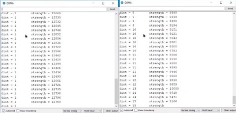
Fig. (13) – LiDAR Range Determined by Microcontroller
SAMPLE RETURN SYSTEM DESIGN
The purpose of the sample return system is to get samples from Psyche back to earth. The scope we decided on focused on the capsule, specifically the heat shield and some of the electrical systems for navigation.
I. Initial Design
For the sample return capsule’s initial design very, general geometries were used. Loosely basing it off the Osiris-REX mission and the shape of several other capsules that have been used. This design, like that of Osiris-REX is built to use aerobraking to reduce its velocity. The process of aerobraking is where you use the atmosphere and drag to slow down your vehicle. Instead of using thrusters for all of your braking maneuver. The initial design is a concept which incorporates all the basic parts of the capsule’s hull. Such as the heat shield which helps during re-entry, the backshell which is a heat resistant material but does not have to ablate like the heat shield, and the inner body which helps the capsule to survive the structural loads of reentry. The heat shield was initially designed and made to an arbitrary thickness at 4.5 inches thick in the initial design. This is optimized as we moved forward with our project.
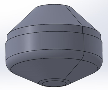
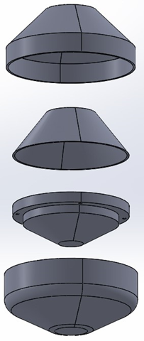
Fig. 1 Initial Capsule Module
The primary function of this initial design was to give us something to work with that was tangible and not just a generic idea of what we were doing. It also served as a framework for future changes and modifications to have a base to work off.
II. Further Research
To know how thick the heat shield needs several variables are needed. This is because of how ablative heat shields work. To mitigate heat transfer through the shield to the vehicle they have small particles ablate and fly off taking the heat that particle has absorbed with it. Therefore, the heat shield will “shrink” as it is used.
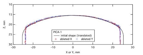
Fig. 2 Pica Heat Shield Ablation Diagram
To know just how much, the time that the capsule will be moving through the denser atmosphere at hypersonic speeds is needed. Once that is known, the information can be combined with experimental data of how quickly that heat shield ablates under those conditions to find how much of the heat shield will shrink.
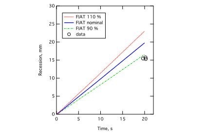
Fig. 3 PICA Heat Shield Ablation Rate
Using the data from the above figures we were able to find that the rate that the heat shield ablates as 1 mm/s (0.03935in). The capsule will be in the atmosphere under extreme heat for roughly 120 seconds.
Therefore, the heat shield will lose 12cm (4.7in) to ablation. This value assumes that the capsule would be under extreme heat the entire time when, in reality, the heat would reduce over time due to the capsule slowing down as it goes further into the atmosphere.
III. Final Design
After having done the math accounting for the ablation we increased the thickness of our heat shield to 5 in instead of 4.7 in. This is a conservative estimate that should give us a decent factor of safety in case anything unexpected were to happen. We kept the backshell the same thickness because it is not under the direct heat of the plasma that is created while moving through the atmosphere. This final design will be used for atmospheric reentry and have the electrical incorporated into it.
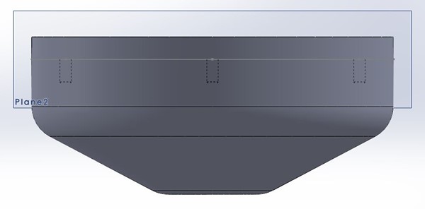
Fig 4 Original Heat Shield Design
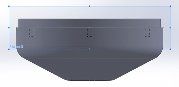
Fig 5 Final Heat shield Design
Light Intensity Tracker (Sun Sensor)
Fig. 6 – Green Display when Photoresistor sense light
Fig. 7 – Red Display when Photoresistor sense no light
When it came to design system like this with Arduino the main thing was that it had to detect difference in light intensity. That is how the photoresistor was selected. This tiny little component can sense the change in light intensity. When it came to wiring this application, it required a power of 5 volts and had to be grounded along with analog port to read the captured data. The basic design for the photoresistor is shown above in the figure. The captured date was gathered and observed to see what the sensor was reading when the sensor was covered to simulate darkness and then again with light to simulate sun light. This was used to create a output based upon these parameters. The output required output ports form the Arduino and resistor for the LEDs. The basic design for the output H2 signal whether the photoresistor is sensing light or complete darkness. The design for the original kind of follows the digital sun sensor mentioned before because it really is only reading two possibilities of no light which is 0 and the possibility of light which is above 0. So, in short to make it more digital zero would be zero and the possibility of light would be one. When light is sense, the Arduino will have an output of an LED light that is green meaning good which is what ground control would see. When there is no light in the sensor is at 0 readings the output would be a red light meaning bad and that the thrusters need to turn on to spin and the correct orientation of the space craft. These two outputs are what ground control would see and be able to measure using the sun sensor and the inertial measurement machine to see if the spacecraft is in the correct orientation if the internal computer was able to fix the problem or more work is needed to fix the problem. The code for this is shown below it uses a very simple C program that is if or else if statement that work to produce an output based off the captured readings in real time.
Accelerometer
Fig. 8 – 3-D Rendering
When it came to using an Arduino to mimic the effects of an inertial measurement machine the idea that the idea that was hatched was to use a component that could replicate the accelerometer effect of the inertial measurement machine. For that it required an Arduino nano and, in a ADXL345 chip which was the accelerometer component within an Arduino kit. The base of the design is simply just tracking the movements within the X, Y, Z of a graph. These movements are measured to see the effects that could happen within the capsule. These measurements are captured and gathered to read the output so that the readings can be seen and fixed or corrected if needed. To add to the project, design a 3D rendering was performed using another database that allows for the readings of the Arduino in real time to be shown on a 3D model. This gives us the side of communication in the way that the spacecraft in space would be able to communicate the movements of the capsule along with the samples to ground control. The 3D model that will show the rendering of the movement of the Arduino used a simple code it just had to be fixed to meet the criteria that I needed for it to output. As you move the urge we know, and the program is running you could see that the program of the 3D model mimics the movement of the adrenal as you move it up and down. This machine allows for ground control to be in control of how much care is taken when moving in space. The effect of the inertial measurement machine can make or break whether a sample gets back to earth intact. This allows for full samples to return and not fragmented ones because as the 3D model seen on ground is shifting a lot, they can adjust the thrusters of the spacecraft and fix it before any of that becomes a factor. The programming of the 3D rendering is shown below and really all it requires is the USB port that is used for the Arduino to be put into the code so that it can read the same port it allows for the 3D model in real time to follow the Arduino’s movements.
Fig. 9 – X,Y,Z coordinates determine form Microcontroller
Fig. 10 – Output of Light intensity tracker form Microcontroller